The design of a non-vented road drift consists of several elements: the body of the drift, the approach road, the upstream protection of the stream, and the downstream apron. These are important structures for retaining water in dry riverbeds. This annex describes the design of non-vented drift, based on the work undertaken by the Kenya Rural Roads Authority.
The drift approach roads should be extended by 10 m on either side of the riverbank on rivers with spans equal to or greater than 50 m and by 5 m on rivers with spans of less than 50 m. The approach road should be extended above the experienced flood level to prevent damage at the road end when the floods are high. The figure below shows a non-vented drift with design considerations.
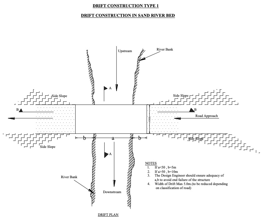
Figure 1. General overview of a drift crossing a sandy riverbed with design considerationsDuring construction, excavation should be done to a maximum of 1.5 m below the existing riverbed level in sandy riverbeds. In rocky riverbeds, the foundations should be laid on the bedrock.
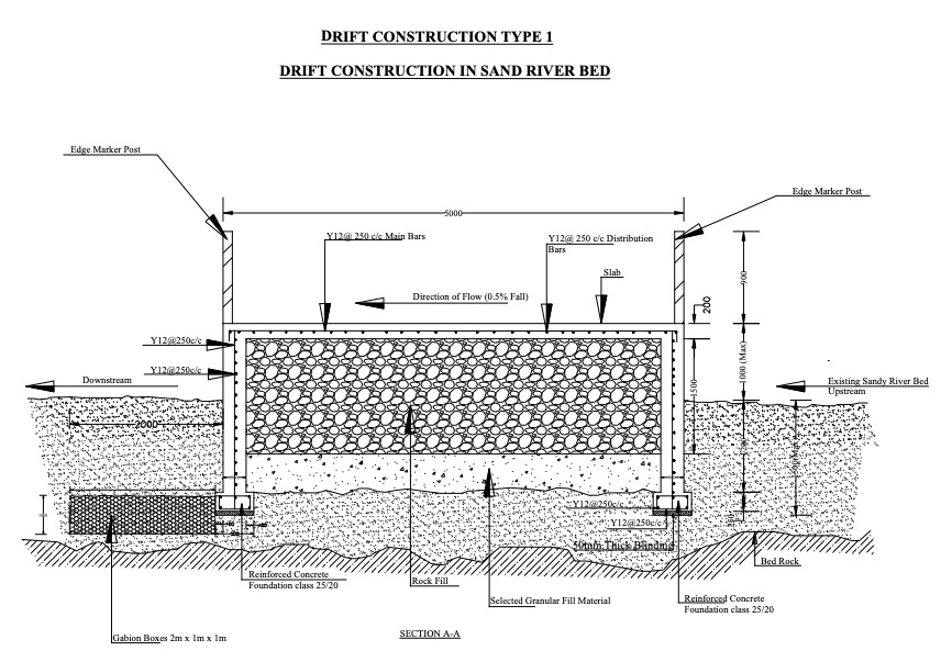
The foundation is the bottom of a structure that is formed by both side walls. Foundations should have a minimum width of 500 mm and a depth of construction of 250 mm. Figures 2 and 3 show the general cross-section of a non-vented drift. Figure 4 shows the longitudinal profile of the drift.
The walls should be 300 mm thick. The top slab, i.e. the top layer (on which traffic passes) should have a constructed thickness of 150-200 mm, depending on the traffic volume and typical load. The drift should be filled with hardcore material and compacted to a maximum depth of 1 m on sandy riverbeds and 0.6 m on rocky riverbeds. Single-layer size Y12 reinforced steel bars should be fixed at a spacing of 250 mm both for main bars and distribution bars. The foundations, walls and the slab should be rigidly tied together to give the drift strong resistance to being washed away by floodwaters. The width of the roadway slab should vary between 3 and 5 m, depending on the type and volume of the anticipated traffic. The height of the drift above the existing riverbed should be a maximum of 1 m to ensure sufficient depth for the accumulation of sand and water upstream. The height of the drift should not exceed 1 m because there will be additional costs and the likelihood that such a retaining wall will also accumulate finer particles, thereby failing to achieve the maximum water-storage capacity.
Gabions should be installed at the foundation of the drift on the downstream side to prevent the undermining of the foundation by the overflowing of floodwater. The drift should have a curvature toward the center of the river to ensure that the water concentrates in the middle of the river, thus minimizing erosion along the riverbank and at the outer ends of the drift. The curvature should also be gentle enough to spread the floodwater over the width of the drift while not extending to the riverbanks.
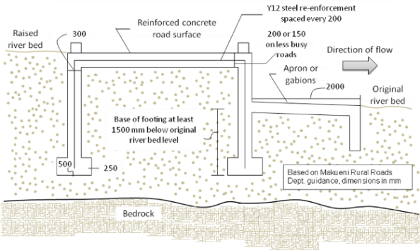
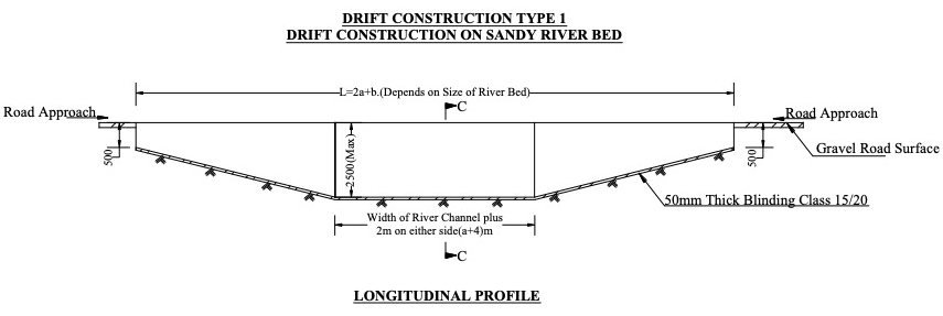
Table 2 below shows the dimensions of a drift.
Table 2. Dimensions of a drift
| Excavation in riverbed | Elevation above riverbed | |
| Large drift in sandy riverbed | Up to1.5 m | 0.5-1.0 m |
| Large drift constructed on bedrock | On bedrock | 0.5-1.2 m |
| Small drift constructed on ordinary river channels. | 0.5-1.0 m | 0.3 m |
| Small drift (road slabs) constructed on swampy plains | 0.5 m maximum | 0.2 m maximum |
Additional retaining walls
Additional retaining walls can be constructed on the upstream and downstream sides of the drift to increase sand and water collection. The walls can be constructed as reinforced concrete or as gabions. Gabion walls are generally constructed at the upper parts of the river course and concrete walls at the lower parts of the river, as the concrete walls are stronger and resist the strong forces of floodwater.
Figure 5 below shows the general arrangement for the design of a water-retaining wall. Figure 6 shows the longitudinal profile of a water-retaining wall.


Gabion mesh boxes measuring 2.0 m x 1.0 m x 1.0 m are also used as retaining walls in the upper parts of the river course to act as erosion-protection works and water-retaining structures.
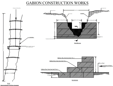
Figure 7 shows the general design arrangement of gabion works on a riverbed.
The elevation of the drift and the walls above the riverbed determine the additional material deposited and the amount of water retained. Coarse material is deposited in the riverbed, while finer material is washed off the drift and walls to areas downstream of the river. The deposition takes place over a number of years until the drift and walls are filled. Their height can be increased later to increase storage and adjust river levels. It is important to ensure that only coarse material is accumulated; this material has the greatest capacity for water storage. Therefore, the drift height should not be too high when it is first constructed, and it is recommended that the drift height be raised in stages to add a layer of coarse material each time.