There is a range of techniques for harvesting water from roads in semiarid areas and different types of storage. This section discusses the main water harvesting techniques.
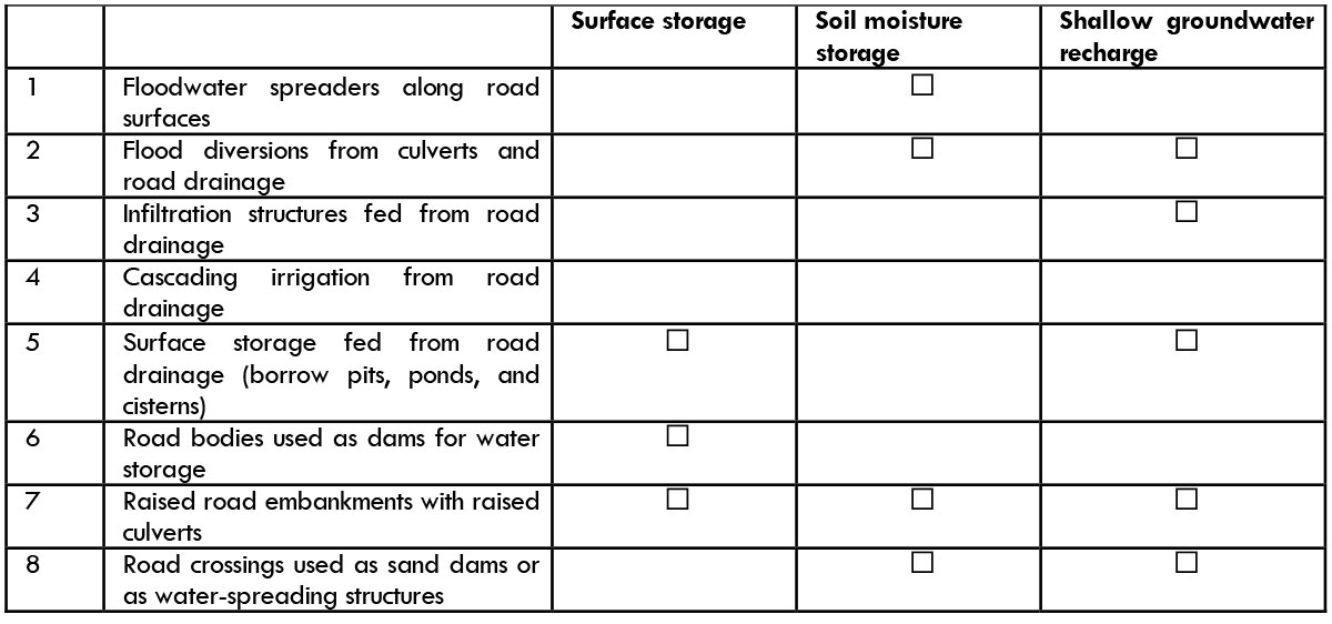
Table 2.3. Roads and water harvesting techniques
2.3.2.1 Floodwater spreaders along road surfaces
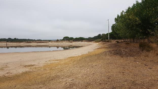
Water can be harvested directly from the road pavement. Within the repertoire of road-water harvesting, this is a minor technique. In most cases water is harvested from the entire landscape (not just the road surface) with the help of road embankments and drainage systems.
A well-graded and compacted surface will generate a conspicuous amount of runoff water. Asphalt-paved roads have a rainwater collection efficiency (RCE, or runoff coefficient) of 0.65 to 0.75 (ERA 2011). For an unpaved road, the RCE varies more, from 0.25 to 0.30 in semiarid areas to 0.80 during heavy storms. This means that if during the year rainfall is 500 mm, 350 m3 may be collected from a 20 m by 50 m stretch of paved road. In humid or sub-humid areas, due to the frequent rain and higher soil moistures, the RCE from unpaved roads is higher. Runoff generated by the road surface can be diverted directly to farmland, recharge areas, or storage ponds through the use of drainage techniques.
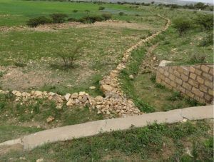
A common technique is to have a series of floodwater spreaders alongside paved road surfaces. These will guide the runoff from the road surface to farmland immediately adjacent to the road and contribute to greater soil moisture. These spreaders consist of low (30 cm) curved structures made of local material that can be used for collection. They are inexpensive to build but need to be rebuilt annually.
There is legitimate concern that water collected from paved road surfaces may have a high proportion of hydrocarbons and other pollutants from traffic. This makes the use of water from the road surface generally unsuitable for human or animal consumption. The degree of pollution is a function of traffic intensity and regular rainfall. Measurements were made along a paved highway section in Ethiopia, but the levels of oil and grease were not detectable (Woldearegay 2016). Nevertheless, areas with heavy traffic should be avoided for direct road-water harvesting: the pollution from hydrocarbons and oils may prohibit the reuse of road water.
2.3.2.2 Flow diversions from culverts and road drainage
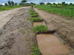
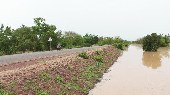
Road drainage systems concentrate runoff. Culverts, in particular, are the embodiment of the changed drainage pattern that comes with road development. Because they concentrate runoff, there is always the risk of erosion downstream of the culverts. Gullies so created may even “creep” upstream and destroy the road body. Therefore, both to protect downstream land and to make beneficial use of water, runoff should be diverted from the culverts.
This also requires that the design of road culverts be optimized in terms of dimensions and appurtenant structures. Research on 15 culverts by Weldu (2018) along the Freweyni-Hawzien-Abraha-We-Atsbeha road in Tigray (Ethiopia) found that erosion could be reduced by 15 percent and water harvesting potential increased by 25 percent with changed designs.
The modification concerned:
Culvert sites on gentle sloping catchments
- Artificial settling basin on the natural stream
- Longitudinal guide structure that keeps the runoff in the original channel bed to avoid flooding
Culvert sites on moderately sloping catchments
- Redirection of runoff through newly excavated channel upstream
Culvert sites on steeply sloping catchments
- Upstream artificial enlargement of the channel width.
- Downstream drop structures with end of bed load settling basin
Different auxiliary structures may be constructed to gently divert flow from culverts to where water will be used or conserved. The structures may be constructed from different materials with different alignments, widths, and heights. V-shaped flood diverters are, in most circumstances, most appropriate, because they dissipate energy from the culvert runoff. If the flow from the culvert comes at low velocity, a diversion structure will be sufficient. The structures should also be placed at a reasonable distance of at least 3 m from the culvert outlets to avoid creating sedimentation inside the culvert.
On steep slopes, the flows from the culverts have high scouring potential and should ideally be provided with energy dissipaters at a safe distance (to avoid full flow condition in the barrel of the culvert). The flow diversion structure should then be placed next to the energy dissipater.
2.3.2.3 Infiltration structures fed from road drainage
The purpose of cross and side drains is to evacuate water away from road structures. This is often done without taking into consideration the opportunities for water storage or recharge. Water from road drains, either culverts or lead-out ditches (or mitered drains), can be guided directly to groundwater recharge structures. Most common are infiltration trenches, recharge wells, and infiltration ponds.
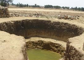
Infiltration trenches are quite popular in Ethiopia and have contributed to rising groundwater levels. Wells are in use in several areas where there never was groundwater before. Infiltration trenches consist of a chain of individual percolation ponds with water overflowing from one pond to the other. This keeps trenches in steep terrain from being scoured out, but instead allows water to overflow from one pond to the next in the trench. Typical dimensions for a single percolation pond in a trench are 1.5 m long x 0.4 m wide x 0.5 m deep. The infiltration trenches should be placed at a safe distance of at least 20 m from the road body on the downhill side to keep them from soaking the soil and affecting the road subgrade. Alternatively, the infiltration trench is led away from the road body.
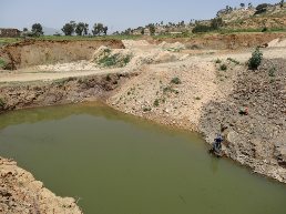
Alternatively, runoff can be guided to recharge wells or percolation ponds. These collect the water for recharge in the shallow aquifer. In some cases, these may be abandoned dugwells or out-of-use borrow pits. Importantly, these recharge structures penetrate a water-bearing layer with good transmissivity (ability to convey water) and spare storage capacity (not saturated). Such conditions are easily found in most semiarid areas.
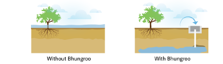
A further sophistication to improve infiltration is the use of special tube recharge wells, or bhungroo as they are called in Gujarat, India. These recharge wells collect excess water during the rainy period and are best situated in areas that are temporarily inundated. The land is slightly tilted toward the recharge well, so that it “feeds” it with water. The bhungroo are equipped with small cemented collection structures measuring 1.5 by 2 m. The top of the recharge pipe sticks out of the bottom of the collection unit to prevent the entry of sediment and dirt. The recharge pipes are between 30 m and 100 m deep, and between 10 cm and 15 cm in diameter. They should penetrate into a sandy layer within this depth: the slotted screen will be placed here. In the case of groundwater use, in shallow aquifers the cost of pumping up water for agriculture may be prohibitive.
2.3.2.4 Cascading irrigation fed from road drainage
The water from road drainage may also be applied directly on the land. This can be done through a single leveled ditch at the top of the field that homogenously spills water to the field downstream, preferably by furrows. This prevents water coming from the road drainage system from immediately submerging the crop and causing damage. The field needs to have a very even, continuous gentle slope to avoid erosion and water ponding. A variation on this comes from relatively level humid areas where the single road ditch is also used in two ways: (i) during rainy periods as a drainage ditch collecting excess water, and (ii) during dry periods as the source of supplementary irrigation.
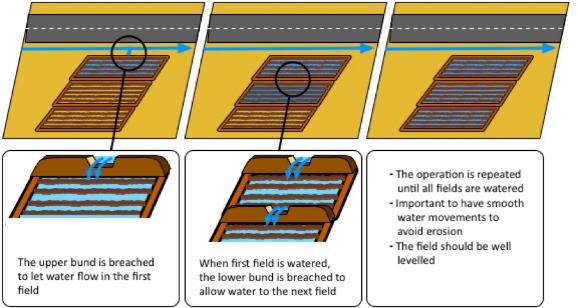
A more elaborate system is when a cascade of fields is served by the water collected from the road. The fields are divided into sub-basins. Water is allowed in the uppermost basin. Once filled, its retaining bund is breached to allow water to enter the next field downslope. This system is commonly used to grow rice in slightly undulating areas.

Alternatively, water can also be routed to a series of planting pits that are connected to each other by ditches. Once a pit is filled, water continues to the next pit. This system is typically used to grow high-value trees. What is important in these three systems is that there is a degree of control at the intake: not all road drainage water is necessarily used.
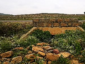
2.3.2.5 Surface storage fed from road drainage (borrow pits, ponds, and cisterns)
Road runoff can also be collected in surface storage: small ponds, dams, borrow pits, or cisterns. Borrow pits can be systematically used as recharge, storage, or seepage ponds. These pits are excavations of source materials—sand, gravel, soil—for road construction and are usually located very near the road itself. The planned “second life” of borrow pits is discussed in Chapter 7. Another option is the development of ponds for road-water storage, as discussed in detail in Chapter 10. Cisterns, i.e., covered storage, are also possible. Because of their higher cost, they are used for domestic water or high-value productive use (see Chapter 6).
2.3.2.6 Road bodies used as dams
Road bodies can also be used as dam walls when the road is made with fill. They can act as:
- Dam walls creating storage by blocking valleys;
- Side embankments of reservoirs; or
- Guide bunds channeling water to storage ponds.
In particular, when roads double as dam walls or side embankments, some concern about their safety is warranted and all safety measures related to dams should include regular inspection of seepage and cracks, provision of spillways and emergency escapes, and protection from damage by livestock or rodents.
The functioning of storage reservoirs should be safe and the road itself should not be undermined. This may require special side protection through clay sealing, riprap, or geotextile.
2.3.2.7 Raised road embankments with raised culverts
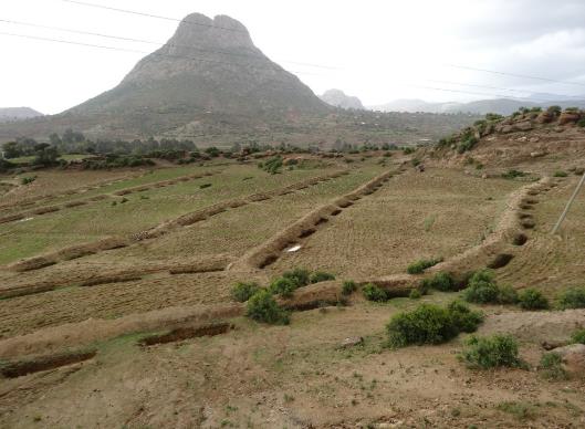
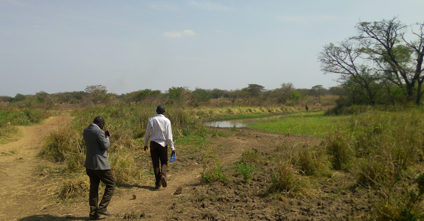
A variation on the use of road embankments for water storage is the used of raised road embankments with raised culverts. The idea is that in semi-arid areas the raised embankment placed in drainage path or depression areas will retain water run-off that can be used in surface storage or recharge or in improved soil moisture. This can be used for improving grazing areas or wetlands, as the example here from North Uganda. The culverts in these road section are raised as well, the level from the ground defining the storage area.
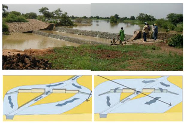
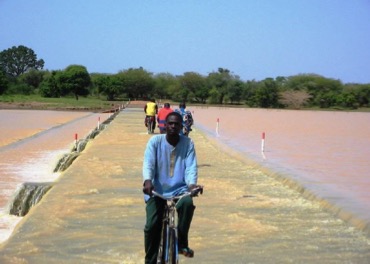
2.3.2.8 Road crossings used as sand dams or as water-spreading structures
When roads cross dry riverbeds or water streams, it is common to construct drifts (also known as low causeways, fords, or Irish bridges). These road crossings can help retain groundwater upstream of the road crossing and can increase bank infiltration. These structures can have multiple functions. The first obvious function is to allow road traffic to cross the dry riverbed. However, the drifts can also double as a proxy sand dam, trapping coarse sediment behind them and creating small local aquifers that can store and retain water. Fords combined with roads also have another function, which is to stabilize the beds of dry temporary rivers.
Depending on the depth of the riverbed, the fords will also slow subsurface flows and retain groundwater upstream, allowing the development of wells or the construction of infiltration galleries to access the water retained upstream of the ford. This capacity to store and retain shallow groundwater is highly relevant in arid regions and improves water access and availability. Chapter 10 provides a detailed description.
A closely related technique is the use of water-spreading weirs combined with river road crossings. These have been developed with considerable success in several Sahelian countries such as Niger. With water-spreading weirs, temporary floods are routed out of the dry riverbeds to inundate the surrounding area. The water-spreading weir serves as the main river crossing, whereas the floodwater is further spread by roads connecting to the weir/river crossing. In this way, the combination of the river crossing as well as embanked roads leading to them act as flood spreaders. Drop structures and cross drainage are provided to the water-spreading weirs to ensure their stability. Arid and semiarid environments are thus regreened with forest and grass species (GiZ and KfW 2013).