Water bars and drainage dips are the main low-cost solutions to provide basic drainage for unpaved roads. They are inexpensive and should become standard elements of unpaved road development and maintenance. They will preserve these ubiquitous low-volume roads and help turn the runoff from the road into a productive asset.
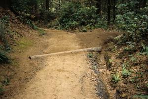
Water bars are narrow structures akin to speed breaks or speed bumps. While their primary purpose is to divert water from the unpaved road surface, not to reduce driving speed, they also serve this purpose.
The specifications for the implementation of water bars are as follows:
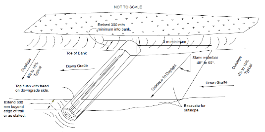
- The position of the water bar should be at an angle to the road direction, preferably between 45o and 60o (out-slope to daylight). Water bars are prone to clogging if they are at less than a 45o angle to the road direction.
- Typically, water bars have a height of 75 mm to 150 mm with a width of 0.3 m to 1 m (see Figure 9.1).
- Water bars may be made of soil, but in very loose soil they can be made of reinforced material: rock, timber, and pre-cast concrete. In the case of prefabricated structures, two-thirds of the structure needs to be embedded in the road body (see Figure 9.2).
- For optimal erosion and runoff control, the ideal number of water bars that should be constructed depends on the slope or road grade. The greater the slope, the less space there should be between water bars. In the case of highly erodible roads with many aggregates of less than 2 mm material, the distance may be further reduced (see Table 9.1).
Table 9.1. Spacing of water bars (after Packer 1967)
| Road grade % | General space between water bars (m) | Space between water bars in highly erodible roads (m) |
| 2 | 75 | 45 |
| 5 | 40 | 25 |
| 10 | 25 | 15 |
| 15 | 18 | 11 |
| 20 | 14 | 9 |
| 25 | 12 | 7 |
| 30 | 10 | 6 |
- The outer extremes of the water bar need to be extended at least 300 mm beyond the road tread.
- The outflow end remains open to avoid accumulation and preferably leads to land where the water will be used for farming or pasture. The runoff should not flow directly to a stream.
- The outslope of the road must be between 6o and 10o.
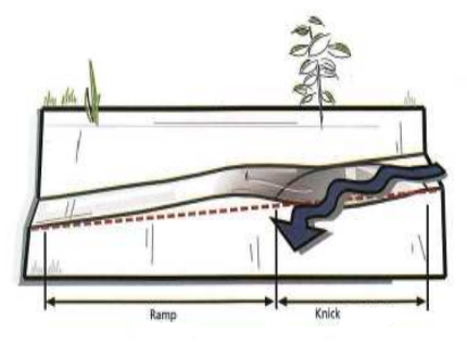
Another drainage feature, closely related to water bars, are rolling dips or drainage dips. Different from a water bar, they consist of a small depression and a pushed-up hump, akin to a water board. The excavated material from the dip is used to create a higher area in the unpaved road, causing the road to slightly undulate, creating a double drainage feature of dip and ramp.
Rolling dips (Figure 9.3) are the most reliable cross drains for low-standard roads. They collect surface runoff from the roadway and/or road ditch and direct the flow across and away from the roadway. The main features are:
- Rolling dips are used to drain low-volume roads with grades between 3 percent and 15 percent.
- The minimum slope of 3 percent is to ensure that the velocity of flow is sustained through the dip. This prevents puddling that would damage the road and keeps sediment moving through the dip drain. Part of the road and the adjacent areas is excavated (for at least 30 cm) to lead the road runoff to adjacent land.
- If the road grade is too steep (greater than 15 percent), the rollout will be too steep on the downhill side and traffic will damage the structure.
- The drainage dips are placed at an angle to the road, similar to water bars. They should have a cross slope of 4 percent to 8 percent. This is steep enough to flush away accumulated sediments.
- The size and criteria for spacing drainage dips are similar to that of water bars, discussed above.